How to Write your own Flight Controller Software — Part 1
Drone flight controller software written in C++ for the Arduino Nano family of boards.
Why would You?
It is a reasonable question. There are a number of Open Source and proprietary quadcopter flight controllers with firmware available. The problem is we want to use an Arduino board, to fit in with our other training programs. As soon as this becomes a constraint your options are very limited. In fact, your only real option is to write your own. So here we are.
Initially we attempted to port BetaFlight across to the Arduino Portenta H7, as this is designed for STM32 hardware and we know that writing your own flight controller firmware is tough and time consuming. We managed to get BetaFlight to compile for the H7 but because Arduino’s use a custom bootloader which is located right where BetaFlight normally sits in memory, flashing the firmware was problematic. The lack of access to the BOOT and debug pins doesn’t help. We will keep working on that project but we need something that we can fly now, so the Nexgen Flight Controller software program was born.
The Hardware
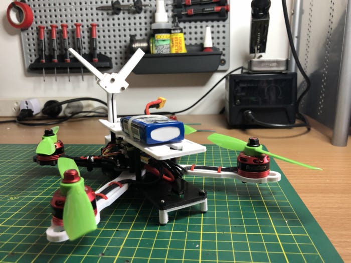
We will continue to use the 3D printed frame for our prototype (Figure 1). As the design matures, we will try a few different configurations to work out what is best. One of the issues with the current design is when you crash, you invariably break an arm. This requires the entire drone to be disassembled in order to replace the arm. Ideally you could just unbolt the arm and re-bolt a new one without having to remove the entire flight stack.
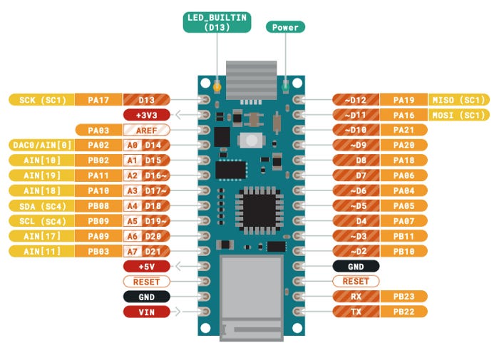
Our target flight controller boards will be the Portenta H7 and the Nano 33 IoT and BLE boards. Unfortunately the H7 uses the MKR form factor while the 33 series use the nano form factor (which is narrower and has an extra row of pins). This means that we will need to redesign the Power Distribution Board and Sensor shield for the Nano’s. The Nano’s do come with a variety of sensors (albeit connected via I2C), so we will try to use those first.
We will use the same quad ESC, brushless motors and radio receiver as utilised in our earlier prototypes. The drone block diagram, showing the components, connectors and options is illustrated in Figure 2. The sensor selection is based on which Arduino is used as the controller.
Flight Controller Theory
When talking about quadcopters there are two common layouts, “X” and “+”. The “+” layout is simpler to model mathematically, but this configuration gets in the way of a camera. Our design (Figure 1), utilises the X layout.
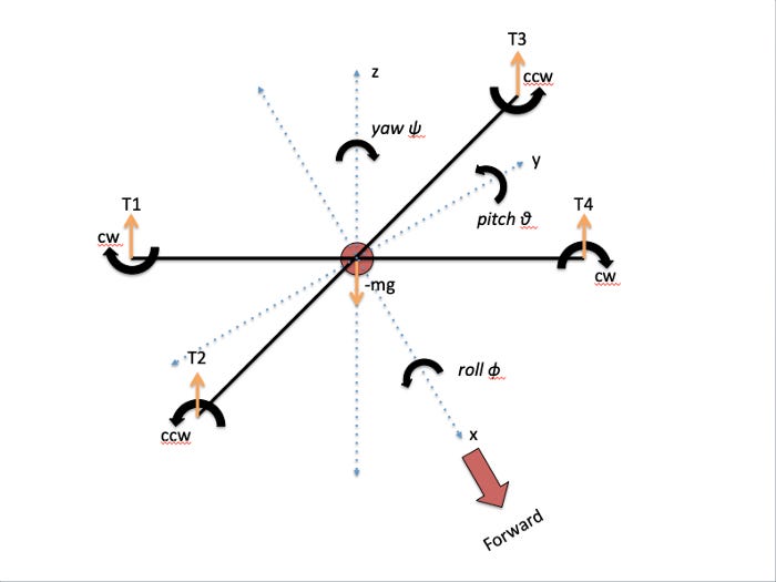
Before writing a control algorithm, we need to mathematically model how drones fly. To do this, we need a frame of reference. A simplified free body diagram is shown in Figure 3. In engineering, a free body diagram is a graphical illustration used to visualize the applied forces and reactions on a body in a given condition. Our diagram ignores the effect of drag and wind (amongst other lesser effects).
The free body diagram illustrates the thrust vectors from the four motors (T1 to T4) offsetting the effects of gravity (Newton’s 2nd Law, F = ma = mg). The only way to control our drone is by altering the speed of the 4 motors, this translates to throttle, roll (x axis), pitch (y axis) and yaw (z axis) effects.
Another way of looking at this, is that all the thrust forces are in the z direction. The implication being that the quadcopter cannot transverse the x and y plane without rotation (i.e. roll, pitch and yaw).
We will operate our remote control in mode 2, which will transmit desired motor speed (thrust), roll, pitch and yaw. Our flight controller algorithm must interpret these and convert them to PWM duty cycles for [T1, T2, T3, T4]. When the controls are released we want the drone to self level. We will need additional sensors to allow the drone to maintain a specific altitude or fly autonomously.
The control system needs to be able to deal with external inputs (e.g. wind) which might prevent the drone moving to the position requested by the remote control. This is normally done using a series of PID (Proportional–Integral–Derivative) loops. These are control loops that update based upon the error observed between a desired output and the measured output.
The control loop’s response is characterized by coefficients Kp, Ki, Kd and is shown in Equation 1 where e represents error and u(t) represents the PID output. The magnitude of coefficients Kp, Ki, Kd determines how responsive the controller is to proportional, integral, and derivative errors respectively. We can use these to tune our PID loop for a desired response. In a drone this manifests in how twitchy the controls are. For acrobatics you want very quick control reactions whereas for filming you want a smoother response.
A visualisation of the Flight Controller system is provided in Figure 4. Here u(t) is the remote control input to the drone, r(t) is the desired set point (or final position) of the control, and e(t) is the error between the output of the drone control and the desired set point. We will need separate PID loops for each control (i.e. throttle, roll, pitch and yaw).
The IMU provides the drones current orientation. This is compared with the desired orientation from the remote control and an error produced. The PID control provides the PWM duty cycle input to the quad ESC which should correct this error by adjusting the thrust provided by the four motors.
ESC PWM Motor Control
To achieve stable flight, it is recommended that our PID loop be running at a minimum frequency of 100 Hz. We want our PWM control signal to be as fast as our ESC can handle, so standard out of the box PWM wont cut it.
We are using the Racerstar BLHeli_S 20A Quad Electronic Speed Controller. The maximum PWM frequency available on BLHeli_S is 48 kHz, if you are using the latest firmware. Previously, the maximum was 24 kHz. All else being equal, a faster PWM frequency should deliver a smoother flight, cooler motors and lower current draw (i.e. increased flight times) due to reduced braking force on the motors.
For maximum speed and flexibility we will control the MCU registers directly. Unfortunately, as the nano 33 IoT, BLE and Portenta H7 all use different microprocessors, this code will need to be unique for each board (or does it?). The default PWM frequency on the 33 IoT is 732 Hz and for the 33 BLE is 500 Hz, so how can we increase this frequency?
Nano 33 IoT — SAM D21 MCU
The Nano 33 IoT main processor is a low power Arm® Cortex®-M0 32-bit SAMD21 running at 48 MHz. This is a 3.3V board and can run multiple loops at once, using the Scheduler library.

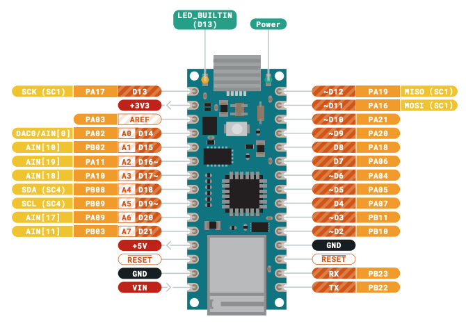
For the four motors on our quadcopter, we have selected the following pins on the 33 IoT:
M4 — D4 (PA07): T1C1;
M3 — D5 (PA05): TCC0 CH 1;
M2 — D6 (PA04): TCC0 CH 0; and
M1 — D7 (PA06): T1C0;
These are all on the same timer (TCC0) but use different channels so we can adjust the duty cycle independently. They line up nicely with the control inputs to the Quad ESC on the left hand side of the PCB.
The formula for calculating single slope PWM frequency is:
PWM frequency = (frequency GCLK) / (N * PER + 1)
where:
log = log to the base 10We could write our own library to set these registers up but it has already been done, It is called the Arduino SAMD21 turbo PWM Library. We will fork this library, take out the stuff we don’t need and produce a wrapper API that will allow us to control the three separate boards with the same commands. We have called this derived library MagpiePWM. To get 48 kHz PWM on the Nano 33 IoT we set the timer for PWM to be the generic clock divided by 4 with a resolution of 250 (single slope PWM).
The Nano 33 BLE and Portenta H7
The advantage we have with these two boards is that the Arduino Core sits on top of the Mbed OS. ARM Mbed OS is a real time open-source embedded operating system designed specifically for IoT.

We can used the mbed::PwmOut function to set the frequency and duty cycle of PWM on these boards. Simple!
Thrust Calculations
The completed Quad is shown in Figure 1. It weighs around 360g. From Newton’s 2nd law, we know that the effect of gravity on the drone is:
F = ma = 0.360 x 9.8 (acceleration due to gravity) = 3.528 NThis is the amount of force required to hover. We want our drone to be able to hover at 50% throttle (or 720 g of thrust). 720 grams of thrust equates to 180 grams of thrust per motor for a quad. The amount of thrust generated by a drone is dependent on the motor and propellers. We are using the Racerstar Racing Edition BR2205 2300KV Brushless Motors. Figure 7 provides us with the details for our motors with the 5045 props. We have to extrapolate the 2S (7.4 V) values but it will be at least 200 g, so our design should have enough power.
During flight tests, our initial prototype had power to burn, thus confirming our calculations. The required thrust is application dependent. For example a racing quad would want a thrust to weight ratio of greater than two, while a cinematic drone could get away with less than that.
Correlating PWM Speed and Thrust
To correlate PWM duty cycle input to the ESC vs thrust, we have to measure it. The usual approach is to build a rig which holds the drone upside down on a weight scale. You can zero the scale and then as you adjust the PWM duty cycle, measure the grams of thrust on the scale.
In Part 2 of this series we will work out how to take controls from our radio control transceiver and apply them to our ESC via PWM.


