

How to Write your own Flight Controller Software — Part 2
How to Write your own Flight Controller Software — Part 2
Adding some necessary hardware…

A Diversion down Hardware Lane
Before proceeding with the flight controller software, we need to sort out a couple of hardware issues. These are, controlling a buzzer (i.e., a passive piezo) and understanding remote control inputs via SBUS.

The Buzzer Issue
Why can’t we just connect a piezo to a pin on our Nano and use PWM to create a tone? I’m glad you asked! The biggest problem is current limits on the I/O pins. If you have a look at the pinout information for the Nano 33 IoT, you will see that the maximum current per pin is 7mA. For the Nano 33 BLE, maximum output current is 15 mA, maximum input current is 5 mA and the maximum total current for the MCU and all GPIO’s is 25 mA.
We have selected the PS1440P02BT Piezo (Figure 1) as our noise maker. The data sheet doesn’t provide the current rating for the piezo, possibly because it varies with the voltage used. For 3.3V, the typical maximum current drawn for these devices is 9–14 mA, which is too much for our Nano. Thus we need to drive it via a transistor. Our buzzer driver circuit is shown in Figure 2.
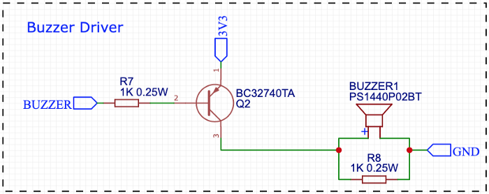
The piezo acts a bit like a capacitor, so we need to place a 1K resistor in parallel with it, to allow it to discharge. Without this, the volume is barely audible at 3.3V. The transistor is a common PNP BC327, which we are using as a switch. When the base emitter voltage, VBE > 0.6V the transistor turns on (saturation), and when VBE < 0.6V the transistor turns off (cutoff). In our schematic, pin 1 is the emitter and pin 2 is the base, thus VE = 3.3V.
This transistor can handle up to 800 mA of collector current (pin 3), which is heaps for our purposes. We can check this by doing some simple calculations.
If the piezo draws a worst case of 14mA, it has an equivalent DC resistance of:
RP = 3.3 / 0.014 = 236 ΩOur total transistor resistance (RL) is RP in parallel with R8 = 191 ohms. Thus our collector current will be:
IC = VCC / RL = 3.3 / 191 = 17.3 mA (i.e. no problem).To work out the base resistor, we can use the following approximation.
R7 = (VCC — VBE) / (IC / 10) = (3.3–0.7) / (0.0173 / 10) = 1503 ΩSo a 1.5k resistor will work. As we are using the transistor as a switch, there is no harm in pumping a bit more base current than we need to ensure sufficient collector current, so we went with a 1k resistor.

As shown in Figure 3, the volume varies with the frequency. The maximum sound pressure level is around 4 kHz. In the test sketch that we put together, operating near the resonant frequencies makes a significant difference to the volume.
Software to Drive the Piezo
Normally you would use PWM to drive your piezo buzzer, and this is what we did initially. However, the Nano 33 BLE only allows you to connect PWM to four pins. If you attach a fifth pin you get the orange SOS of death. PWM is more important for motor control than driving a buzzer so we came up with an alternative approach.
It took me a while to track down this issue as it isn’t well documented and in fact the Arduino site states that any digital pin can be used for PWM. This may be the case, but only four pins at a time. The Mbed PWM function is where the limitation is arising from, so you could get around this by writing your own PWM function.
To get around this limitation we wrote a function which emulates PWM using bit banging. It is not as good as PWM at higher frequencies but it gets the job done.
UPDATE — While trying to debug the issues we were having decoding SBUS (described in the next section), we came across the Tone class. This uses timers and has a nicer sound than our version, so we will go with that.

The SBUS Protocol
In the old days you would take PWM control data from a pin on your radio control receiver, with each pin representing a channel on your remote control transmitter. A channel could be throttle, yaw, pitch, roll, etc. It is now more common to use a digital protocol to transmit this information. An example of this is SBUS (Figure 5). The protocol is designed to condense 16 individual channels into a single data frame.

The SBUS protocol was developed by Futaba to control servos with each channel assigned to a different servo. It is based on RS232 but to make life difficult they inverted the signals (i.e. 0 = VCC and 1 = GND), put the most significant bit first (UART has LSB) and used a non-standard baud rate of 100,000. The other configuration details are (8E2):
1 start bit
8 data bits
1 even parity bit
2 stop bits
Each SBUS message is 25 bytes long and takes 3 ms to be transmitted. A Futaba transceiver in analogue mode will send a message every 14 ms, and in high speed mode, every 7 ms. The FrSKY transceivers generally send a message every 10 ms. A message consists of:
A header byte (0x0F);
16 x 11 bit channels (total of 22 bytes);
1 flag byte, which includes two digital channels [0 0 0 0 fail_safe frame_lost ch18 ch17]; and
1 footer byte (0x00).
Each of the 16 channels can have a value in the range of 172–1811, which we will map to 1000–2000.
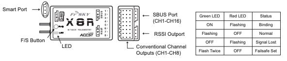
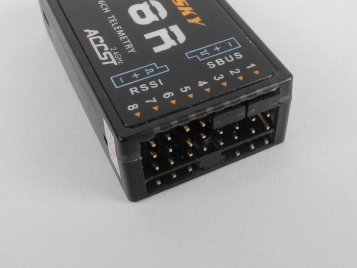
We are using the FrSKY X8R Remote Control Receiver (Figure 4) which provides 8 channels using PWM or 16 channels via SBUS. It also gives us signal strength via the RSSI pin and we can transmit telemetry over the Smart Port connection. FrSKY SBUS is inverted compared to Futaba SBUS.
Binding the Receiver to the Transmitter
Binding is the process of uniquely associating a particular receiver to a transmitter module. A transmitter module can be bound to multiple receivers. A receiver can only be bound to one transmitter module.
The steps below are the binding procedure for a FrSky X8R receiver. If you are using a different receiver then the binding procedure will be different (read the manual).
IGNORE the instructions in the X8R manual — they are confusing!!
Disconnect the battery from the drone.
As shown in Figure 7, insert the jumpers across the signal pins of channels 1 & 2 and channels 3 & 4. This will configure the receiver as mode 4 (Figure 8). The Flight Controller will use SBUS on CH1-CH16 and the 8 PWM outputs exposed on the X8R will be controlled using CH9-CH16 (which we aren’t using at the moment). The different modes of the X8R are set by a combination of the pins with jumpers and whether the F/S button is pressed while powering on. Mode 4 also provides telemetry which is what we want. Alternatively, leave the jumpers off to get mode 5, which will also work for how we want to use the receiver.
Power on the Taranis Transmitter and edit the flight model. Select mode D16 and the number of channels that you want to use. The mode names are a bit misleading, D8 refers to the older D series transmitters with up to 8 channels and telemetry, but without Model Match and Failsafe. These features are only available with D16, which offers a maximum of 16 channels. There is no reason for using D8, except if you are using an older transmitter which does not support D16. Otherwise, D16 is the way to go, even if you only transmit 8 channels.
The transmitter and the receiver need to be at least 1 m apart or you may get transmission errors. When you are ready, press bind in the transmitter setup menu.
Power up the X8R while holding the F/S button on the module (Figure 4 — if you want mode 4). Release the button. The RED LED on the X8R module will flash, indicating the transmitter is ready to bind to the receiver.
Turn off both the transmitter and the receiver. Remove the jumpers on the X8R
Turn on the transmitter and connect the battery. The GREEN LED on the receiver indicates the receiver is receiving commands from the transmitter. The receiver/transmitter module binding will not have to be repeated, unless one of the two is replaced.

Inverting SBUS
We captured an SBUS packet from the FrSKY X8R using our protocol analyser (Figure 9). From this you can see that it is the opposite of what Futaba SBUS expects (i.e. normal!), LOW is GND and HIGH is VCC (5V).

We need to invert this signal to get a Futaba compatible SBUS packet. In addition, the FrSKY X8R is generating 5V logic and our Nano pins are not 5V tolerant. Consequently, we need to shift the voltage down to 3.3V before feeding the inverted signal to the Nano (Figure 10).

The output of this circuit is shown in Figure 5. The top channel of the protocol analyser is showing the SBUS signal straight out of the FrSKY X8R and the bottom channel is showing the inverted signal from the transistor (INV SBUS in Figure 10). This looks perfect because the protocol analyser is cleaning up the signal and showing a purely digital result. We need to have a look on the oscilloscope to see what is really happening.

Figure 11 illustrates the direct FrSKY output on the scope. It isn’t too noisy and the transistions are fairly sharp. Interestingly, even though the X8R is powered from 5V, it seems to be outputting logic at 3.3V (ish). Things are a bit more ropey when we look at the inverted output from the transistor (Figure 12).

In Figure 12 we see that the logic transistions are not quite as crisp as the protocol analyser would have us believe. The rise time has gone from 1 µs to 4 µs, in the next section we will determine whether this matters.
Arduino SBUS Library
There are a number of Arduino SBUS libraries but none compatible with the Nano 33 BLE or Portenta H7. The most complete is the one from BolderFlight. This library works with Teensy 3.x and LC devices, the STM32L4, the Maple Mini, and ESP32. Our mission — to get it working on the Nano 33 BLE and the Portenta H7.
We tried the easy option first, since it looked like it should work. We just added the appropriate board definition in the SBUS::begin() function, as follows:
#elif defined(ARDUINO_ARCH_NRF52840) // Arduino Nano 33 BLE _bus->begin(_sbusBaud, SERIAL_8E2);We have connected SBUS from the X8R (inverted) to the Rx pin on Serial1 of the Nano 33 BLE. The code above effectively calls Serial1.begin(100000, SERIAL_8E2), thereby setting the baud rate to 100000 and the configuration to 8 data bits, even parity and two stop bits. There are two problems:
Setting a non-standard baud rate will be rounded down to the next lowest standard rate (see Figure 12); and
The default serial configuration is 8 data bits, no parity, and one stop bit (8N1). Trying to set anything else will cause Mbed OS to crash. This is a known issue.
if (baudrate < 2400) {new_rate = NRF_UARTE_BAUDRATE_1200;}
else if (baudrate < 4800) {new_rate = NRF_UARTE_BAUDRATE_2400;}
else if (baudrate < 9600) {new_rate = NRF_UARTE_BAUDRATE_4800;}
else if (baudrate < 14400) {new_rate = NRF_UARTE_BAUDRATE_9600…         Figure 12. Extract from serial_api.c (reference).
It is possible to set a non-standard baud rate and configuration by accessing the appropriate registers for the nRF52840. For example, to set the configuration:
UART0 Base address 0x40002000
UART CONFIG register address offset 0x56C
Therefore register address we want to modify is 0x4000256C
From page 479 of the Product Secification, we want to set:
STOP = 1 // Two stop bits; and
PARITY = 0x7 // Include even parity bit
So we want CONFIG = 0x0000000F. For the baud rate (reference):
UART0 Base address 0x40002000
UART Baudrate register address offset 0x524
Baudrate formular according Nordic devzone:
Baudrate = desired baudrate * 2³² / 16000000
The relevant updates to the SBUS library are as follows:
#if defined(ARDUINO_ARCH_NRF52840) // Arduino Nano 33 BLE    // Serial1.begin() wont set a non-standard baud rate and
    // anything but 8N1 crashes Mbed OS.    const uint32_t CONFIG = 0x000000F;
    const uint32_t sbusBaudRate = 0x19114A7;
    uint32_t *baudRateRegister = ( uint32_t * )0x40002524;
    uint32_t *configRegister = ( uint32_t * )0x4000256C;
#endif/* starts the serial communication */
void SBUS::begin(){
    // initialize parsing state
    _parserState = 0;
    // initialize default scale factors and biases
    for (uint8_t i = 0; i < _numChannels; i++){
        setEndPoints(i,_defaultMin,_defaultMax);
    }

   // begin the serial port for SBUS
   #if defined(ARDUINO_ARCH_NRF52840) // Arduino Nano 33 BLE
      _bus->begin(9600);
      *baudRateRegister = sbusBaudRate;
      *configRegister = CONFIG;
   #else
      #error unsupported device
   #endif
}
The SBUS “channels” variable in this library is a zero-based array, so channels[0] is actually SBUS channel 1, and so on. The default channel layout on the Taranis Q X7 controller is TAER, and this is what we will use:
T = Throttle (channel 1);A = Aileron (channel 2);E = Elevator (channel 3); andR = Rudder (channel 4).Monitoring Battery Voltage
When flying a drone one of the critical parameters is battery voltage. If the battery gets too low our drone will fall out of the sky. Less dramatically, we may want to adjust our motor inputs as voltage decreases. Battery Compensation applies an initial motor output reduction when the battery is full, and boosts motor output upwards from that value during the flight, to compensate for reducing battery voltage. This delivers a more consistent stick feel, both for throttle and PID, over the usable battery voltage range. The drone will not feel super aggressive at the start of a flight, or dull at the end.

The analog inputs on the Nano 33 BLE can handle a maximum of 3.3V, thus we need a voltage divider to reduce our battery voltage to an acceptable level. Figure 13 illustrates the voltage divider circuit provided on the Magpie Power Distribution Board. The resistor values are appropriate for a 2S LiPo. If you are using something different then you will need to adjust this. The calculation is as follows:
Fully Charged 2S LiPo = 8.4 VMax Pin Voltage = 3.3 VVbat = Vin x R4 / (R3 + R4)where:
Vbat is the input to our analogue pin; andVin is our battery voltage.If we assign a nominal 10k to R4 then R3 = 15.5k, which we round up to 18k for a safety margin and to get a standard value. For our calculation of Vbat to be accurate, we need these resistor values to be accurate so use 1% resistors for R3 and R4. You can use this online voltage divider calculator to play around with different values.
If we rearrange the equation above, we get:
Vin = Vbat(R3 + R4) / R4 = Vbat * 2.8We can use this to calculate the current battery voltage but first we need to convert the analog input value read into a voltage.
The Arduino Nano 33 BLE has 8 analog input pins (ADC 12 bit, 200 ksamples). We have assigned pin A0 (nRF52840 pin PA02, ADC0) to measure our battery voltage and will use the Mbed function AnalogIn.
AnalogIn() reads the voltage as a fraction of the system voltage. The value is a floating point number from 0.0(VSS) to 1.0(VCC). For example, if you have a 3.3V system and the applied voltage is 1.65V, then AnalogIn() reads 0.5 as the value.
The resolution for an ADC is the smallest distinguishable change in analog input that causes the digital output to change. For example, a 12-bit ADC in a 3.3V system has 4,096 distinguishable outputs. Therefore, the resolution of a 12-bit ADC is 3.3/4096 = 0.81mV. This is more accuracy than we need.
Rather than do the calculation, there is another Mbed function which returns the value as a voltage, read_voltage()which returns a float. This is what we will use.
There is a diode between Vusb and Vin to stop a reverse voltage into Vusb from Vin. When Vin is larger than Vusb the board is powered by Vin and Vusb is disconnected. You can test out our example sketch called battery voltage by just connecting the Nano via USB and you will get close to 4.9V (which sounds correct). If both the USB and the battery is connected we read 8.45 V, which is correct for a fully charged 2S LiPo.
Stay Tuned…
In Part 3 of our series we will display our radio control inputs in Processing and connect our RC controls to the PWM ESC code so that we can start controlling the motors. This will then be combined with our IMU data and a PID loop to complete our base flight controller software.