

How to Write your own Flight Controller Software — Part 4
How to Write your own Flight Controller Software — Part 4
Our next challenge is feeding the error signal e(t) for roll and pitch into our PID loop and then outputting a corresponding PWM control signal to drive our four motors.

In Part 3 of our series on writing your own flight controller software, we looked at PID control and what that consists of. When writing complex software, it is usually easier to break it down into smaller parts which you can test independantly. Our path to functioning flight control firmware on an Arduino looks like this:
Pilot input (i.e. decoding SBUS);
Gyroscope output;
PID control loops; and
Motor mixing and motor output.

In researching best practice PID control loops for quadcopters, it quickly became apparent that there are a number of different approaches to how you can implement these. Our initial thinking was that we were trying to correct for position so we would use pitch, roll and yaw angles (Figure 1). While this can work, the main issue is that it is difficult to tune the PID loop so that the drone flies in a stable manner.
In addition, the Arduino Nano 33 BLE uses the LSM9DS1 as its Inertial Measuring Unit (IMU). This has a 3 axis digital linear acceleration sensor, a 3 axis digital angular rate sensor, and a 3 axis digital magnetic sensor. In order to get angle data we were using a complementary filter to combine sensor data from the gyroscope and accelerometer. The data coming directly from the gyroscope is an angular rate, in degrees per second. For a PID loop, the best parameter to calculate the error for, is the parameter that you want to control.
Furthermore, the drone propellers produce a force perpendicular to their plane of rotation. This force is related proportionally to the propeller’s angular velocity. For each propeller,
T = k⍵

where T = Thrust (force), k = constant (drone dependent) and ⍵ = angular velocity.
A quadcopter is an under actuated system. This is because we have 4 actuators (i.e. motors) and 6 degrees of freedom — three translational directions, up and down, left and right, forward and backwards, and three rotational directions, roll, pitch, and yaw. As we don’t have an actuator for every motion, we know that some directions are uncontrollable at any given time.

As all the thrust forces are in the z direction (i.e. up), the quadcopter cannot transverse the x, y plane without some rotation. For example to go forward you need to pitch the drone down. The important point is that the output of our PID controller is ultimately another angular rate.
For these reasons, we will implement the approach shown in Figure 2 which features cascading PID loops. The other advantage of this approach is that it gives us two flight modes (rate and stabilise), which can be selected by the pilot.
Iterating the Design
Based on the arguments above we need to revisit some of our earlier design choices. For pitch and roll pilot inputs we were mapping the SBUS payload from the remote control of 172–1811 to -60° to +60°. For throttle we mapped to a range of 0–100. If we are going to use angular rate instead, then we need different mapping.
We will need to tweak these values following flight tests, but the suggested maximum input rates are around ±180°/s to ±250°/s for roll and pitch and ±270°/s for yaw for full stick deflection.
There is nothing we need to change regarding the Gyroscope output except we will use the angular rate data rather than the derived angle from the complementary filter. This work wont be wasted though, the complementary filter will be required for Stabilize mode.
By the way, it is not unusual (or bad) to have to iterate on a design. In fact it is probably more likely than not.
Rate Mode
The most basic multi-rotor flight mode is known as rate, gyro or acro mode and only uses the gyroscope for flight feedback. The basis of quadcopter stabilisation is the 3-axis gyroscope measuring the rate of rotation, for example degrees per second for the roll, pitch and yaw axes. Rate mode won’t automatically level your drone, but it does provide the most free-flowing flight from a pilot’s perspective.
We will get the drone flying in rate mode before we attempt Stabilize Mode.
Stabilize Mode
To automatically level the quadcopter known variously as auto-level, stabilize or angle mode, requires it to know which way is up. This is achieved using a 3-axis accelerometer that measures gravity. This time the pulses from the RC receiver’s roll (airelon) and pitch (elevator) channels are converted to an angle, say ±45°, (again using the Arduino map function).
Yaw is still controlled using rate, say degrees per second as before. The roll and pitch inputs act as the setpoints to the corresponding outer roll and pitch angle PIDs, whose outputs are then in turn used as the setpoint to the inner rate roll and pitch control loops. The measured input to these two outer PIDs comes from an estimation of your roll and pitch angle (in degrees). This is achieved by fusing the angle calculated from the integral of the gyroscope (degrees/s * time = degrees) with the angle calculated from your 3-axis acclerometer outputs. It’s possible to do this using a complementary or Madgwick filter.
The reason for fusing the gyro and acceleromter outputs is that the gyroscope is stable in the short term, but drifts over time, while conversely the accelerometer is noisy in the short term, but gives a stable angle estimation over time. By combining the two you can overcome their deficiencies.
The effect of auto-level mode is to automatically level the quadcopter when your sticks are released.
Motor Mixing
There needs to be a way to combine the output from the pitch, roll and yaw PID loops and the throttle input from the remote control, to give us the control signals to the four motors. This process is call motor mixing.
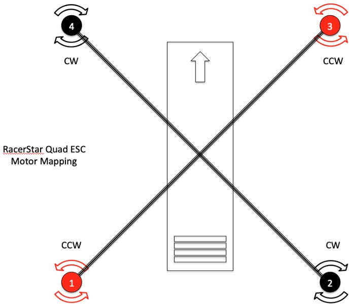
We can command thrust by setting all four motors to the same speed. Then we can create yaw by increasing two motors spinning the same direction and decrease the other two. Pitch is created by increasing or decreasing the front motor pair and then commanding the back pair in the opposite direction. Roll is the same, but with a left/right pair. Our simple motor mixing algorithm that can convert between the roll, pitch, yaw, and thrust, and motor speeds is shown in Figure 4. This uses the motor mapping definitions shown in Figure 3.

There are two ways to account for the maximum throttle. The traditional way has been to limit the throttle to say 90%, thereby giving your motor mixing some headroom, when adding the roll, pitch and yaw from the PIDs. The latest method is to detect the amount by which the motor mixing exceeds the maximum throttle, then reduce the throttle to allow the addition of the PID outputs to stay withing the motor’s maximum.
Flight Code
Now that we have settled on a control system architecture we can commence coding. In Part 7 of this series we will put together the flight code. This will include the following components:
Rate Controller;
Drone State (sensors);
Motor Mixing;
Failsafe; and
Data Logging.
In Parts 5 and 6 we will have a detailed look at the IMU, how to get the best roll, pitch and yaw information and why calibration is so important. This is a necessary detour as this data is a key input to our PID loops and determines how well we can self level.