How to Write your own Flight Controller Software — Part 3
In Part 3, we will look at the roll, pitch and yaw inputs from the IMU and combining that with r(t) to get our error signal , e(t), which is fed into our PID loop.
The PID Loop
In Part 1 of our series we spoke about the flight controller PID Loop. It is worth revisting that now (see Figure 1). In previous parts we have spoken about how we decode the remote control input, r(t), and how we generate our PWM control for the ESC, u(t). In Part 3, we will look at the roll, pitch and yaw inputs from the IMU and combining that with r(t) to get our error signal , e(t), which is fed into our PID loop. We will output the desired setpoint and PID loop output to the Nexgen Configurator to assist with tuning.
The Flight Controller loop design will determine how well our drone flies and how aggressively the control inputs are converted to motor outputs. By tweaking the parameters of our PID loop we will be able to produce a flight model which is slow and stately or fast and agile. Which is appropriate depends on the purpose of the drone mission. If you are doing cinematography you dont want a lot of abrupt changes but if you are flying acrobatics you do.
In addition to tweaking the gain constants in our PID controller, we can adjust the response of our flight model by having different modes. For example:
Rate or Acrobatic Mode — which uses only feedback from the gyroscope in the PID loop and doesn’t attempt to self level; or
Stable Mode — which uses both gyroscope, accelerometer and magnetometer (if available) to help smooth the flight model. You would also normally self level in this mode.
Some Theory
The objective is a control system which adjusts the output to meet a desired state, often called the setpoint. The PID controller is a closed loop system. That means it uses feedback from its sensor to work out if the output is the same as the setpoint. Unlike simple control algorithms, the PID controller is capable of manipulating the process inputs based on the history and rate of change of the signal. This gives a more accurate and stable control method.
As shown in Figure 1, our Flight Controller determines the state of our drone using the IMU. For example, the gyroscope will tell us the amount of roll. This is compared with the input from our remote control, in this example the amount of pressure on the right hand stick (assuming a mode 2 setup on our transmitter). The difference between these two inputs is the error signal e(t). The error will be managed in three ways; to handle the present through the proportional term, recover from the past using the integral term, and to anticipate the future through the derivate term.
The amount of each component (P, I and D) used is determined by the gain or weighting on each element. This is designated as Kp, Ki and Kd.
With proper setting of the weighting in a PID circuit, you can achieve a relatively quick response with minimal overshoot (passing the set point value) and ringing (oscillation about the set point value).
The Proportional Term
Like the name suggests, the proportional term (P) gives a system control input proportional with the error (Figure 2). Larger proportional gain results is larger changes in response to the error, and thus affects the speed at which the controller can respond to changes in the system.
While a high proportional gain can cause a circuit to respond swiftly, too high a value can cause oscillations about the set point value. Too low a gain and the circuit cannot efficiently respond to changes in the system. If the P weighting is too high you will get an unstable system.

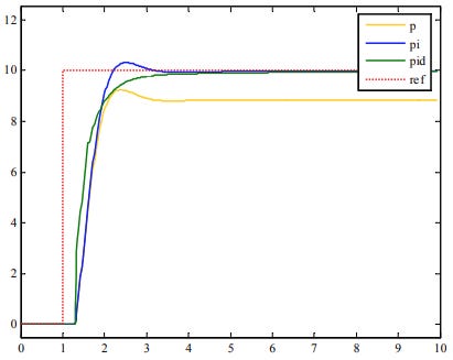
As illustrated in Figure 2, using just proportional control will leave a constant offset from the set point. Thus we need to add a new term to correct for this.
The Integral Term
The integral term (I) adds the sum of the previous errors to the control input. The summing of errors will continue until the system output equals the set point, and this results in no offset error when the reference is stable (Figure 2 — pi). However, due to the fast response of integral control, high gain values can cause significant overshoot of the set point and lead to oscillation and instability. Too low a gain, and the circuit will be significantly slower in responding to changes in the system.
The Derivative Term
Derivative control attempts to reduce the overshoot and ringing output from proportional and integral control. It determines how quickly the circuit is changing over time (by looking at the derivative of the error signal) and multiplies it by Kd to produce the derivative response. A rapid change in error will give an addition to the control input. This improves the response to a sudden change in the set point and the derivative term is essentially a high pass filter.
Unlike proportional and integral control, derivative control will slow the response of the circuit. In doing so, it is able to partially compensate for overshoot as well as damp out oscillations caused by integral and proportional control. High gain values of Kd can cause the circuit to respond very slowly and leave it susceptible to noise and high frequency oscillation (as the circuit becomes too slow to respond quickly). Too low a Kd and the circuit is prone to overshooting the set point. However, in some cases overshooting the set point by any significant amount must be avoided and thus a higher derivative gain (along with lower proportional gain) can be used.
Figure 3 shows the effect of increasing the gain of any one of the parameters independently.

Combining the terms as a PID controller usually gives the best performance. Figure 2 summarises the output of P, PI, and PID controllers. PI is better than P as there is no offset error, and PID is better than PI due to a faster response and no overshoot.
PID Loop Implementation
Given the universal appeal of the PID controller, it is not surprising that Arduino libraries already exist which implement the strategies outlined above. This allows us to focus on tuning the PID loop for our specific quadcopter design. We will use the Nexgen Configurator, which is written in Processing/Java, to help us visualise the input, outputs and error of our PID controller.
Generating the Error Input
Figure 1 illustrates how the error signal, e(t), is the input to our PID Loop. How do we generate this error signal given our IMU is giving pitch, roll and yaw feedback in degress and our remote control input is an integer proportional to stick movement on our transmitter? In order to compare these two inputs we have to have them both using the same units. In other words we need to map the SBUS remote control inputs to degrees.
If you look at the SBUS library which is part of the Flight Controller firmware runnning on the Arduino Nano 33, you would see the following code in the header file.
This is the minimum and maximum numbers which will be returned as the result of a control input from our Taranis Transmitter (e.g. if throttle = 0, the transmitter will send 172 and if throttle is 100% it will send 1811). The numbers sent in between depend on the response curve programmed into the transmitter for each channel.
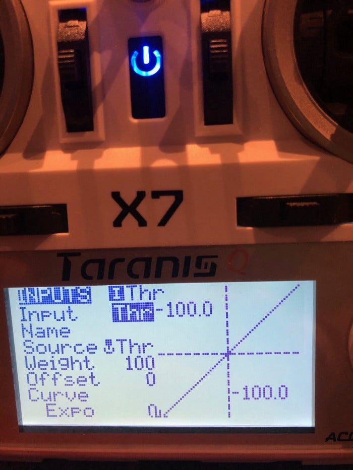
Figure 4 illustrates the throttle response curve that we have programmed into our remote control. Each channel has one of these. You can see that in this instance the curve is linear from -100 to 100, with 0 produced when the stick is centred. This gets converted to 172–1811 by the SBUS protocol, which are the FrSKY defaults. In part 2 of this series we saw that the SBUS payload is a 11 bit binary number. The important point is that there is a linear mapping between the stick input and the SBUS value.
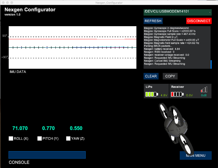
We can verify this by using the Nexgen Configurator (Figure 5) and looking at the SBUS values on each channel for the control inputs. This is found on the Radio Control screen.
In stable mode, we will enforce a maximum bank and pitch angles of 60 degrees, to make the aircraft harder to accidently crash. To work out if left or right bank and foward or rear pitch is positive or negative, we will use the Nexgen Configurator to work out what system the IMU uses. We will use the same system for control authority inputs.
As illustrated in Figure 6, the IMU has:
- Left Bank (or Roll) +ve;
- Right Bank -ve;
- Pitch Up +ve; and
- Pitch Down -ve.
When the drone is parallel with the ground, roll and pitch is zero degrees. Thus we need to map the SBUS control inputs of 172–1811 to -60° to +60°. If the IMU goes past 90°, it gets confused, so even in acrobatic mode we will limit the control input to 80°.
Now that we have normalised the IMU and control inputs, calculating the error signal is simply a matter of subtracting one from the other. For example, the roll error would be calculated using:
e(t) = roll input° — roll position°In Part 4, we will visualise the error signal using Nexgen Configurator, feed it into our PID loop and convert the output to a PWM duty cycle.


